 |
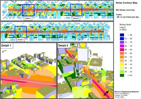
Noise Contouring with the Grid Noise and Grid Cross Section Map Module - The Grid Noise Map comes in two variants, as a horizontal map Grid Noise Maps (1) where the receivers follow the terrain or in the vertical format as Cross-sectional Noise Map (2). Spacing of receivers and height above the ground are user selectable. There is no size limit for Grid Noise Maps, however as SoundPLAN can load an unlimited number of Grid Noise Maps into each sheet, it is probably wise to partition the Grid Noise maps for very big areas. Grid Noise Maps have a whole gambit of output options to generate contour lines and smooth them or to leave the grid in place and show the values or have the grid painted in a fluid scale. |
 |
Cross Section Module Cross-sectional Noise Maps are noise maps that start at the terrain and reach to a user selected height, again the receiver spacing us user defined. This mapping option is very user friendly allowing the calculation to be interrupted and resume later on or to calculate a new grid or to re-calculate only part of the grid. If the single PC with multi threaded calculation proves to take too long for the job, with Distributed Computing (DC description is under Tools) the application is scalable to the need of the user. |
 |
Noise Contour Outputs The user has various ways of presenting the grid results such as:
|
|
|