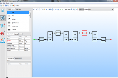
This module models the generation and propagation of low frequency sound in complex duct networks. The frequency range is limited to the plane wave region in the connecting pipes. It is based on linear acoustic theory and all elements, e.g., a complex muffler, are reduced to two-ports while terminations and sources are represented as one-ports. A number of standard elements representing common duct and pipe elements as well as basic muffler types are available as building blocks, which can be connected to form a network. All standard element models are validated and are based on the best and most recent models published in the literature. The users have the possibility to add their own elements as user defined elements.
SIDLAB Acoustics Features
SIDLAB Output Metric
Transmission Loss and Insertion Loss in dB
Noise Reduction in dB, narrow band, octave and third octave
System Resonances
The elements of the Transfer and Scattering Matrices for each element and for the full network
Sound Pressure RMS and phase at each node in the network. (Pa or dB, narrow band, octave and third octave)
Sound Power exchange to and from the network at each node. (W or dB, narrow band, octave and third octave)
Sound Pressure RMS outside the network at a predefined receiver position. (Pa or dB, narrow band, octave and third octave)
Transfer Function between any two nodes in the network
SIDLAB Acoustic capabilities
Work with different unit systems to define the dimensions of the network: m, mm and inch
Save different versions of the design in the same project
The fluid medium can be a perfect gas or a liquid. Available editable library of common fluids
Element Manager: Add new elements, delete elements, and modify their list of properties
The system network can be drawn in 2D or 3D with a variety of drawing and editing tools
Drawing the network in 3D has no influence on the calculation. 3D Networks are only for visualization purposes
Several convenient ways to manipulate the results and export them in different formats
SIDLAB Acoustics special calculations
Engine order vs. Engine RPM calculation: The frequency vector is calculated automatically. Extra needed input data is the inlet flow and temperature at each RPM.
Optimization: Optimize the system performance (TL – IL – radiate pressure) for a range of frequencies using any number of variables. Define equality and non-equality dimensional constraints. Possible to include the allowable pressure drop as a constraint
Parameterization: Choose a single parameter inside the network, perform a parametric analysis by varying the value of this parameter within a specified range with a specified step. The results are shown for all values of the parameter simultaneously
Standard Two-Port Elements
Pipe (Hard walled, can be filled with porous material)
Duct (Rectangular cross section)
Diffuser, curcular and rectangular
Quarter Wave-Length Resonator (can be filled with porous material)
Helmholtz Resonator
Catalyst (decrease the contents of harmful exhaust gases)
Diesel Particulate Filter (DPF reduces the harmful emission of soot particles from diesel engines)
Lined Duct (with porous material)
Sudden Area Expansion and Contraction
Expansion Chamber (concentric extended inlet and outlet)
Orifice
Lumped Element
Perforate (lumped impedance element)
Bend, circular and rectangular
Inlet and Outlet End Caps
User-Defined Transfer Matrix as a function of frequency